
A-131
GPS 天線
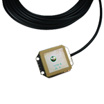 A-131 是一種高性能的GPS天線,它內建電源保護系統與抗RF訊號干擾設計,以保護主動式訊號放大器(LNA)和GPS接收器與連接器連結的一端,使其免於短路的危險(GPS接收器前端往往會因為外部天線超載或短路而遭到破壞或損害)。位於底部的RF訊號保護隔離設備能夠削減噪音並提供更精確的訊號。A-131 可專門做為多功能的整合應用,如GPS追蹤產品等等。天線為標準的電源輸入,電壓範圍從3V〜6V。如同極星所生產的其它天線一樣,A-130 符合RoHS標準,是由高品質的雙重隔離編織層的同軸電纜線和鍍銀中心導針所製做而成。
A-131 GPS Active Antennas is the only innovating design antenna with performance,
quality and a Power protection circuit built-in to protect the active LNA’s, and most
importantly the host GPS receiver down the connector end from the danger of a
SHORT circuit external antenna (Note: GPS receiver front-end can be destroyed or
de-graded by an external GPS antenna in an over-load or short conditions. The A-131
is a low profile GPS active antennas system for the next generation multi-purpose
GPS mobile antenna products for Telematics, Fleet Management, Navigations and
AVL applications. This small print size of the antenna design does not reflect over-all
performance, since the antenna itself needs no ground plane aid to deliver the L1
band small signal carrier that originates from the 24 orbiting USA satellites located
thousands of miles over-head and with the ground reception power sensitivity at over
-130dB. The A-131 GPS Active Antennas is also design as a standard power input
voltages in range from +3Vdc to +6Vdc with reverse polarity shutdown, over-current
sense shutdown and an EMC power line suppression. The most important over-all
design concept of the A-131 GPS Active Antennas is the complete protections of the
host sensitive GPS receiver made from any manufacturer that it serve and can also
be destroy or de-grade using an improper design antenna.
| General | |
| 2 Stages active LNA | |
| Dual Filters, (HPF & LPF(lump element)) | |
| +28dB gain | |
| Dielectric Patch antenna | |
| Low Noise Low drop-out, Linear Regulator | |
| GPS receiver short circuit protect | |
| Low Loss RG/174 Coax cable | |
| Aluminum Base/ PC+ Radome Plastic | |
| Performance | |
| Receiving Frequency | L1 Band(1575MHz) |
| Output Impedance | 50 ohms |
| Polarization’s | Right Hand Circular (RHC) |
| Bandwidth | 10dB Mhz @ -3dB point |
| VSWR | 1.5 Typical @ 1575MHz |
| Elev. Angle Coverage | 5~90 degree |
| Az. Bearing Coverage | 360 degree |
| Filtering | Dual(BPF <10 Mhz B/W, LPF @1576 MHz Stop-band @ 1585MHz) |
| Over-all Gain | 28dB (typical including 4dB cable loss & Filters) |
| Over-all NF | <1.8dB @fo, 2dB max. |
| LNA Characteristic | K=>1 Un-conditionally Stable |
| RF Insertions loss | K=>0.1dB, leakage power 100mW /1 watt input |
| Power Consumption | 11mA to 13mA (max) |
| Power Input Sensor | Reverse Polarity Short Circuit shutdown |
| Over-Current Sensor | Thermal Over-current shutdown >+150degreeC |
| Electrical | |
| Power Input | +3Vdc to + 6Vdc input, Auto Switching |
| Physical | |
| Dimensions | 31 x 24.5 x 7mm +/-0.5mm |
| Mount | Magnetic |
| Radome Color | No |
| Coax Connector | BNC, SMA, SMB, MCX, MMCX, GT-5 |
| Coax Cable | RG-174U double shielded 5m, Low Loss 0.7dB/m |
| Environmental | |
| Operating Temperature | -30 to + 85 degree C |
| Storage | -40 to + 90 degree C |
| Optional | |
| 1. Open Frame Antenna , with RF shield | |
| 2. Open Frame with 3” Flanges & RF shield | |
| 3. Ant + Aluminum Base | |
| File Name | File Size | Time |
| A-131 ARKNAV-Datasheet | 826 KB | Sep 18th 2009 |